بوابة الاتصالات 12.3500/92
The 3500/92 Communication Gateway module provides extensive communication capabilities of all rack monitored values and statuses for integration with process control and other automation systems using both Ethernet TCP/IP and serial (RS232/RS422/RS485) communications capabilities. It also permits Ethernet communications with 3500 Rack Configuration Software and Data Acquisition Software.
Supported protocols include:
The 3500/92 supports the communication interfaces, communication protocols, and other features from the original 3500/90 with the exception of the primary value Modbus registers. The 3500/92 now has a Configurable Modbus Register Utility, which can provide the same functionality originally addressed by the primary value Modbus registers
OK LED: Indicates that the 3500/92 is operating normally.
TX/RX LED: Indicates that the 3500/92 is communicating with other modules in the 3500 frame.
The front and rear views of the 3500/92 communication gateway are shown below:
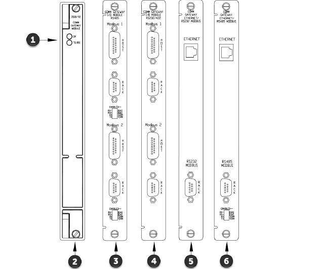
Figure 1: Front and Rear Views of the 3500/92 Communication Gateway
1.Status LEDs
2.Comm Gateway Module--
136180-01
3.RS485 I/O Module--
125736-01
4.RS232/422 I/O Module--
133323-01
5.Ethernet/RS232 I/O Module--
136188-01
6.Ethernet/RS485 I/O Module--
136188-02
3500 System Example
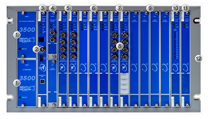
1. Power Supplies: This particular rack has an AC-powered supply in the primary (lower) position, and a DC-powered backup supply in the upper position.--
3500/15
2. Keylock security prevents tampering with the configuration of the monitors in the rack.
3. Transient Data Interface (TDI): Provides an interface to configuration software and to System 1 Condition Monitoring & Diagnostic software. It also coordinates communication between all modules in the rack.--
3500/22M
4. Keyphasor Module: Accepts single and multi-event per-rotation signals from proximity probes and magnetic pickups installed on rotating equipment.
5.
3500/72M
(Recip Rod Position) and
3500/77M
(Recip Cylinder Pressure) monitors are used for condition monitoring of reciprocating compressors.
6.
3500/60
&
3500/61
Temperature Monitors.
7.
3500/42M
Proximitor/Seismic vibration monitors.
8. Buffered transducer signals are provided for use with portable test instruments.
9. Unused slots are protected with “Future Expansion” covers, and are available for use with additional modules.
10.
3500/33
16-Channel Relay Module.
11.
3500/92
Modbus® Communication Gateway.
12. Standard rack for 19” EIA rail mounting
Section 5 Common Problems and Solutions During TSI System Commissioning
Problem:
The speed probe displays a reading at low speeds but not at high speeds.
Possible Cause:
The probe installation distance is too large, exceeding its measurement range.
Solution:
Readjust the probe distance.
Problem:
The speed display is incorrect, showing a reading that is too low or too high.
Possible Cause:
The number of events set in the speed configuration does not match the actual number of teeth on the gear disc.
Solution:
Reconfirm the configured event number.
Problem:
No key phase signal.
Possible Cause:
The key phase cam disc is missing a key phase slot. The installation distance is too large.
Solution:
Check for a key phase slot; if missing, fabricate one on-site. Or adjust the probe distance on-site.
Problem:
The probe display gradually increases or decreases without reason.
Possible Cause:
The quick-connect connector between the probe and the extension cable is grounded.
Solution:
Check the insulation of the quick-connect connector.
Problem:
The gap voltage is consistently displayed incorrectly during probe installation.
Possible Cause:
The probe and extension cable are incompatible or damaged.
Solution:
Check the serial numbers of the probe and extension cable. Or recalibrate.
Problem:
When the temperature of the thrust bearing working surface is significantly higher than that of the non-working surface for an extended period, the shaft phase displacement display shows a negative value.
Possible Cause:
Incorrect shaft phase displacement direction setting.
Solution:
Check the probe installation direction and working surface position; recheck the configuration data.
Problem:
The LED bypass light remains constantly on during normal operation of the card.
Possible Cause:
Card malfunction.
Solution:
Check the data curve of this card's probe for abnormalities, grounding issues, or partial suppression of card functionality; a new card is needed.
Problem:
The probe vibration is unstable and jumps; the vibration curve is not smooth during normal unit operation.
Possible Cause:
The probe is not securely installed; the cable shielding is inadequate, leading to external interference.
Solution:
Check the shielding; check the probe installation.
Problem:
TSI digital and analog outputs are not displayed when connected to other systems.
Possible Cause:
Incorrect signal type design.
Solution:
Check if the TSI signal output type corresponds to its compatible system.
Problem:
The relay has no alarm output.
Possible causes:
The relay module is misconfigured or not activated.
Solution:
Check the configuration.
الكلمات :
عنوان : Unit 1904, No.96-2 Lujiang Road, Siming District, Xiamen
Phone/WhatsApp/Skype : +86 18060982349
بريد إلكتروني : sales6@nseauto.com